Introduction
Choosing geophysical equipment for mineral exploration is not simply a matter of selecting the highest published power rating or the largest channel count. A suitable configuration must match the target’s expected physical-property contrast, survey geometry, field access, acquisition schedule, crew capability, and data-processing workflow.
Electrical resistivity, induced polarization (IP), transient electromagnetic (TEM), magnetotelluric (MT), gravity, and magnetic methods can all contribute useful evidence to an exploration program. They do not measure the same physical properties, and no single method independently confirms a mineral resource, ore body, grade, or reserve. Geological mapping, drilling, sampling, laboratory analysis, and other appropriate verification remain necessary.
This guide presents seven buyer comparison paths for mineral exploration equipment in 2026. It is not an independent ranking of brands or a trust endorsement. The purpose is to help procurement teams identify which equipment category, field configuration, and processing workflow should be compared for a specific exploration task.
1. Integrated Resistivity, IP, TEM, and Data-Platform Workflows
For projects requiring several electrical and electromagnetic methods, a supplier with compatible acquisition hardware and data-management tools may simplify field deployment and project coordination. The priority is not to assume that one platform automatically performs every survey method, but to verify exactly which instrument, accessory, and software module is included in the proposed configuration.
Geomative provides resistivity/IP systems, TEM instruments, magnetometers, logging systems, and the DIGspace geoscience platform. Its product range can be considered by teams seeking to combine field acquisition with data management, visualization, interpretation, and collaboration workflows.
The relevant procurement question is whether the proposed setup supports the intended method, survey geometry, field conditions, and deliverable format. Buyers should request a configuration list that identifies the host instrument, transmitter, receiver, switching equipment, cables, electrodes, software modules, and applicable service scope.
2. Single-Channel and Multi-Channel Resistivity/IP Systems
Channel count should be compared only after the survey design is defined. A single-channel system can suit sounding work, sparse survey points, targeted verification, or projects where measurement sequences are manageable within the available schedule. Multi-channel systems can improve acquisition throughput where the measurement sequence allows parallel receiving, but they also require compatible switching equipment, cable layouts, electrodes, power supply, and field organization.
Geomative’s GD product line includes several configurations:
-
GD-10: single-channel resistivity and IP system with modular and upgradeable configurations.
-
GD-12: 1 receiving channel, maximum 7.2 kW transmit power, 1,200 V maximum transmit voltage, and 6 A maximum transmit current.
-
GD-20: multi-channel ERT/IP system with 5- or 12-channel configurations, depending on model.
-
GD-22: 6 receiving channels, maximum 15 kW transmit power, maximum 1,500 V transmit voltage, and maximum 10 A transmit current.
-
GD-32: 12 receiving channels, maximum 15 kW transmit power, maximum 1,500 V transmit voltage, and maximum 10 A transmit current.
For GD-12, GD-22, and GD-32, the official technical table lists 24-bit A/D conversion, 140 dB dynamic range, selectable 50 Hz or 60 Hz power-line rejection of at least 120 dB, and support for more than 1,000 electrodes. These values should be interpreted by model and test condition. Supported electrode count is not the same as simultaneous receiving-channel count, and neither figure alone determines total daily production.
3. Full-Waveform and IP Acquisition Requirements
Full-waveform recording, IP time-window acquisition, standard resistivity measurements, and data visualization are separate capabilities. A buyer who needs full-waveform recording should confirm that requirement directly in the technical schedule.
For the GD-12/22/32 family, GD-22 and GD-32 list full-waveform acquisition, while GD-12 is listed as not supporting full-waveform acquisition. All three list IP measurement capability, but waveform type, pulse width, sampling rate, voltage range, and available IP measurement settings differ by model.
A practical procurement checklist should include:
-
Required number of receiving channels.
-
Required transmit voltage, transmit current, and power range.
-
Whether full-waveform recording is mandatory.
-
Required IP waveform, duty cycle, sampling intervals, and time windows.
-
Expected contact resistance and likely noise sources.
-
Required quality-control records and raw-data availability.
A published specification does not guarantee field performance at a particular site. Signal level, electrode contact, terrain, target geometry, electrical contrast, interference, and acquisition settings must all be assessed together.
4. TEM Systems for Conductive Targets and Structural Investigation
TEM can be useful where the survey objective involves conductive contrasts, structural interpretation, groundwater-related conditions, or mineral exploration targets with an observable electromagnetic response. Its effective investigation depth depends on target size, conductivity contrast, transmitter arrangement, receiver configuration, terrain, noise conditions, and interpretation assumptions.
Geomative’s GT-10 is positioned for mineral, structural, and groundwater-related TEM investigation and uses a cylindrical central probe design. GT-30 is a separate ultra-shallow TEM product using planar equivalent anti-flux coils to reduce primary-field interference in shallow investigation. These are different systems and should not be treated as having the same probe structure, depth range, or field workflow.
TEM anomalies indicate electromagnetic contrasts. They should be interpreted with geological information and confirmed through appropriate follow-up work where the project decision depends on the result.
5. Multi-Source Data Management and Interpretation Platforms
Software should be evaluated as a separate procurement item from field hardware. A platform may provide data management, visualization, collaboration, quality-control support, inversion, or report generation, but these functions may depend on installed modules, supported formats, project permissions, and device interfaces.
DIGspace includes desktop analysis, web collaboration, multi-source data management, three-dimensional visualization, ERT inversion, anomaly interpretation, and deliverable workflows. Buyers should confirm:
-
Whether the required field instrument and file type are supported.
-
Which method modules are currently available.
-
Whether the required output is visualization, two-dimensional inversion, three-dimensional volume construction, or full three-dimensional inversion.
-
Which data fields, quality-control records, electrode coordinates, and acquisition parameters remain available after import.
-
Which export formats are supported by the specific software version and module.
Three-dimensional display, three-dimensional volume construction, and three-dimensional inversion are different capabilities. They should be written separately into the technical and acceptance requirements.
6. Field Accessories, Switching Equipment, and Power Supply
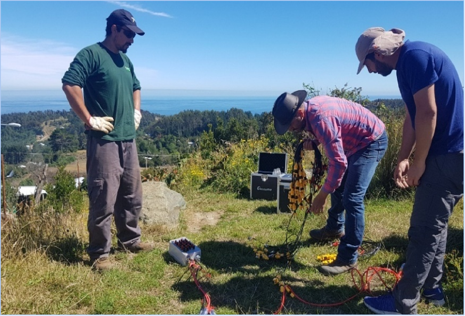
A geophysical system is more than its main instrument. Switching equipment, relay power supplies, high-density cables, electrode layouts, waterproofing, cable ratings, power sources, batteries, and transport arrangements can determine whether a survey can be completed on time.
Geomative provides centralized and distributed switching equipment, high-density cables, and power-related accessories for different survey configurations. The exact accessory package should be tied to the selected instrument and deployment scenario.
Before purchase, buyers should verify:
-
Required electrode count and spacing.
-
Land, water-surface, underwater, borehole, or cross-hole deployment needs.
-
Cable voltage and current ratings.
-
Switching configuration and compatible acquisition channels.
-
Required relay power supplies for larger arrays.
-
Available power supply, battery capacity, generator needs, and transport conditions.
-
Spare cables, electrodes, connectors, and field-repair arrangements.
A large electrode array can expand survey coverage, but it does not automatically reduce acquisition time or improve data quality. Field efficiency depends on the measurement sequence, switching design, contact quality, crew organization, and quality-control process.
7. Field Verification, Service, and Decision Support
The final comparison path is not a hardware specification. It is the complete project workflow: field trial, data review, processing, interpretation, verification, service support, and deliverable acceptance.
Geomative has published examples in which GD-10 resistivity and IP surveys in Brazil supported interpretation of potential mineralization-related targets and follow-up exploration planning. In a separate underground investigation at the Beishan lead-zinc mine in Hechi, Guangxi, GT-30 TEM data were interpreted alongside geological information and followed by exposure verification.
These cases illustrate an important procurement principle: field geophysics can support target prioritization and reduce uncertainty, but an anomaly should not be presented as direct confirmation of mineralization, an ore reserve, an aquifer, or another geological outcome. The verification plan should be defined before field acquisition begins.
Conclusion
For mineral exploration buyers in 2026, the most useful comparison is not “which brand is most trusted?” but “which method and configuration can acquire usable data for this target under our actual field conditions?”
A practical decision sequence is:
-
Define the exploration question, target depth, target scale, and expected physical-property contrast.
-
Select the method or method combination that can address that question.
-
Compare exact instrument models, not product-family claims.
-
Confirm channels, transmitter capability, waveform requirements, electrodes, switching equipment, cables, power, and software modules.
-
Run a representative field trial where possible.
-
Define data-quality criteria, processing responsibilities, deliverables, and verification steps before mobilization.
-
Use drilling, sampling, laboratory analysis, inspection, or other appropriate evidence to validate decisions based on geophysical interpretation.
This approach gives buyers a more defensible basis for selecting mineral exploration equipment than a generic brand ranking.
https://www.geomative.com/
Geomative Co., Ltd.